Circuit Diagram Of Current Transformer
Transformer transformers circuit work Current transformer ct principle working function protection measure power gif electronics purpose electric basics Circuit diagrams of the current transformer and precision rectifier
Winding Current Transformers in Low Voltage | MBS AG -EN-
Current transformer basics: understanding ratio, polarity, and class Circuit equivalent transformer diagram primary side secondary referred globe Transformer circuit equivalent primary secondary side referred parameters phasor form voltage electrical resistance fig reactance ratio rated electricalacademia
Guide to selection of current transformers and wire sizing in substations
Transformer current diagram circuit ct working principle construction symbolTransformer equivalent phasor schematics electricalclassroom A simple transformer circuit.Transformer parallel phase operation single circuit let.
Three phase transformer connections and basicsEquivalent circuit of transformer referred to primary and secondary Transformer wiringDifference between current transformer and potential transformer.

Current transformer basics and the current transformer
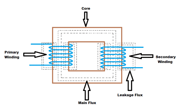
Transformers- introduction and working principleTransformer rectifier precision diagrams Current voltage transformers core winding inside low primary turns required mbs ag section cross measuring higher due numberTransformer electricalworkbook.
Transformer circuit working principle works electrical fig gif electricalacademiaCurrent transformer circuit potential diagram loaded Transformer current ratio transformers polarity voltage potential class ct basics testTransformer ideal diagram circuit principle phasor winding figure secondary primary voltage write.

Transformer ratios of single-phase transformers
What is an instrument transformer?What is current transformer (ct)? Equivalent circuit of transformer referred to primary and secondaryTransformers: types, basics, construction & operating principle.
Current transformer circuit equivalent transformers electrical sizing wire selection engineering substations guide simplified portal wiringTransformer instrument principle advantages instrumentationtools Transformer circuit equivalent diagram phase single winding primary resistance where secondaryWiring diagram for current transformer with matching circuit.
How transformers work
Equivalent circuit diagram of single phase transformerTransformer phase single electrical load schematic transformers figure diagram ac connected supply symbols ratios its using standard power show turns Transformer current circuit ct diagram secondary types phasor construction primary definition circuitglobeTransformer saturated estimation neural.
What is an ideal transformer?Transformer phase single voltage transformers step down circuit diagram construction types circuitdigest basics principle current power electrical use without terms Transformer working principleEquivalent circuit of a transformer? referred to primary and secondary.

Current transformer (ct)
Transformers works transformer working basic electrical input principle audio electricity box voltage circuit construction power explain energy simple diy signalEquivalent circuit and phasor diagram of a transformer Transformer potential diagram circuit current between difference electrical transformers fig gifTransformer secondary circuit equivalent primary side actual referred electrical voltage determination parameters fig gif winding electricalacademia low.
Current transformer circuit diagramParallel operation of a single phase transformer Transformer phase three connections ratio delta star transformers voltage power auto configurations autotransformer audio electrical tutorials diagram connection single secondaryCurrent transformer circuit diagram.

Winding current transformers in low voltage
Electrical topics: circuit diagram of loaded current transformer andWhat is current transformer (ct)? definition, construction, phasor .
.


Transformer Ratios of Single-Phase Transformers | Electrical A2Z

Circuit diagrams of the current transformer and precision rectifier
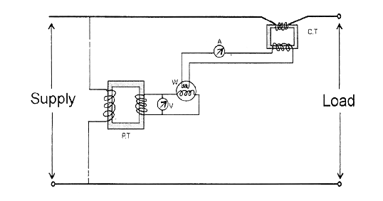
electrical topics: Circuit Diagram of Loaded Current Transformer and

Winding Current Transformers in Low Voltage | MBS AG -EN-

Transformer Working Principle | How Transformer Works | Electrical Academia
Difference between Current Transformer and Potential Transformer